


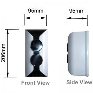
WIRELESS ADDRESSABLE BEAM DETECTOR
FUNCTION
- An optical beam smoke detector is a device that uses a projected beam of light to detect smoke across large areas, typically as an indicator of fire. They are used to detect fires in buildings where standard point smoke detectors would either be uneconomical or restricted for use by the height of the building.
INSTALLATION
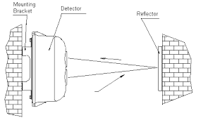
- Setting Length of Optical Pathway: Setting Length of Optical Pathway: When mounting distance between the detector and the reflector is not less than 40m (but not more than 100m)
- Align the detector and the reflector horizontally on the two facing walls in monitoring area, as shown in Diag. C
The detector can be surface-mounted in two ways:
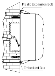
- with conduit Embedded surface-mounted
- Remove the detector's top cover
- Align the base of the detector over the back box and mark the positions of mounting holes on the wall.
- Drill two holes at the marked positions, and push two ∅6 plastic expansion bolts in.
- Thread the wires through the cable entry, ensuring the length of wires inside convenient for connection.
- Fix the detector base on the wall with two plastic expansion bolts and flat washers.
- Mounting method is shown in Diag. D
- Conduit surface mounting
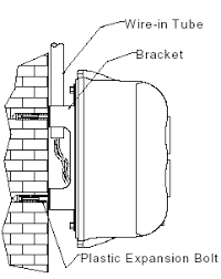
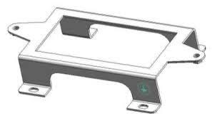
- Put the mounting bracket at position intended to Plastic Expansion Bolt Back Box install the detector; mark the locations of the four holes of mounting bracket on the wall
- Drill the holes on marked positions, and push ∅6 plastic expansion bolts in.
- Fix the mounting bracket on the wall with four ∅6 plastic expansion bolts and flat washers.
- Remove the detector's top cover; thread the wires through the cable entry, ensuring the length of wires inside convenient for connection.
- Fix the detector base onto the bracket with two M4×10 bolts and flat washers.
- The mounting bracket should be earthed through the mounting hole.
- Mounting method is shown in Diag. E
Mounting the Reflector
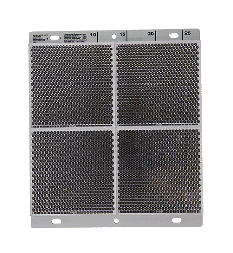
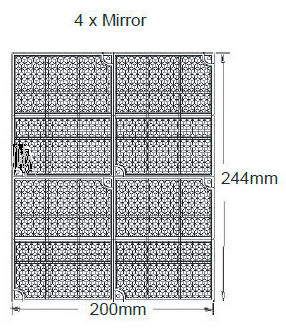
- The reflector is mounted opposite the detector but in line with it. When the distance between the detector and the reflector is more than 8m (less than or equal to 40m), one reflector is enough. When the distance is more than 40m (less or equal to 100m), four reflectors are needed. Two ∅6 plastic expansion bolts are needed to fix a single reflector. If four reflectors are needed, place them seamlessly
Testing and Commissioning
- Take off the protective membrane carefully on the surface of the reflector and the detector. Do not scratch or contaminate their surfaces.
- Remove the detector's top cover, and connect to 24VDC power. Two minutes later, put the magnet of commission tool close to the reed switch (around the red LED) of detector's interface board. There may be two cases with the LEDs:
- Green LED flashes.
- Green LED illuminates continuously.
- If green LED flashes, it means the received light is quite weak (the slower the flashing frequency, the weaker the received light signal is).Tune the adjusting wheel and rotary rack on the detector to align the light beam until green LED is lit continuously, showing that the light received by the detector is strong. Then stop regulating and enter
- If green LED illuminates continuously, it means the received light is quite strong, you can go straight to step 4.
- Note: Observe the detector's optical pathway carefully to ensure that the received light signal is reflected by the reflector rather than by obscurations like wall, ceiling, or pillar. If uncertain, verify by covering the reflector with opaque objects
- Put on the top cover gently, and screw the two bolts on the cover. The green LED illuminates continuously. Put the magnet of commission tool close to the zone where marked M until yellow LED illuminates constantly, then remove the commission tool quickly and make sure there is no obscuration on the optical pathway. About 5 seconds later, the detector begins to adjust automatically. Yellow LED flashing means weak light, green LED flashing means strong light. If red LED, yellow LED and green LED flash alternately, this means the detector failed to adjust automatically and cannot enter normal monitoring state. Please open the detector's top cover and do adjustment from step 2. If yellow LED and green LED illuminate no more, and red LED flashes periodically, this means the detector is at the best position and has entered normal monitoring state. The commission is finished.
Fire alarm test
- After the detector has been in normal monitoring state for 20 seconds, cover the receiving window and emitting window with the IR Light Filter (please use the part for fire alarm test), the detector should report fire alarm in 30 seconds and red LED should turn on
Fault test
- Cover the receiving or emitting window of the detector quickly with the IR Light Filter (please use the part for commission) to obscure the optical pathway. Yellow LED of the detector should be turned on. Taking off the filter immediately, yellow LED of the detector should be turned off.
Failed Detector
- Test again, according testing method mention
- If they fail again, return them to factory for repair.
Cautions
- Power up only after all devices are well connected.
- Adjust the detector after installation and maintenance.
- Under adjusting condition, both the detector loop and fault output contact transmit fault signal
- The detector base should be fixed directly on solid wall or frame that will not be deformed by vibration. Any deformable material such as paperboard, plastic board, foam board or thin wood board should not be placed between the base and the wall or the bracket.
OPERATION
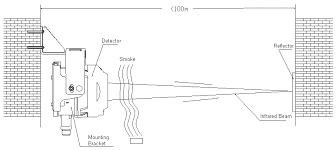
- The detector and reflector are placed oppositely. The detector includes emitting part and receiving part. Infrared beam of certain intensity sent out from the emitting part is reflected by the right-angle prisms of the reflector, and then received by the receiving part of the detector. The receiving part simultaneously collects and amplifies the returned infrared beam, analyze and judge the collect signals through its microprocessor. When the detector is in normal monitoring state, the intensity of infrared beam received by the receiving part is steady at a certain level. When smoke particles enter the detecting area, the intensity of infrared light received by the receiving part falls owing to light scattering. When the smoke particles reach a certain density, and the intensity of infrared light received by the receiving part is reduced below the preset threshold value, the detector alarms fire, illuminates red LED. And fire output contact is closed. If connected with GST control panel, the fire signal will be passed to the panel through loop. Operation principle is shown in Diag. H
AVOID THESE LOCATIONS
- Space height is over 40m
- It is not roofed
- Space height is less than 1.5m.
- There is a lot of dust, powder or vapor.
- It is clean normally, but can be dusty in some special cases.
- Temperature is high. Note: Temperature at top part of a workshop with transparent roof may be over 50℃ when there is sunshine
- There is no access for maintenance.
- The Mounting wall or fitting is greatly affected by mechanical vibration.
- There are fixed or moving objects within 1m from the detector's optical pathway.
- There is strong magnetic field